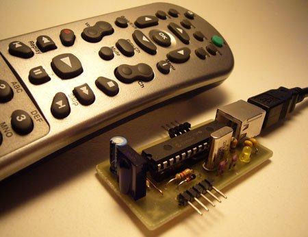
ow that we listen to MP3s, and watch XVIDs or x264s, a computer is the entertainment center in at least one room of most homes. Unless you have a special HTPC, though, you’re probably stuck using the keyboard to pause, change the volume, and fast-forward through annoying Mythbusters recaps. PC remote control receivers range from ancient serial port designs (who has one?) to USB devices not supported by popular software. In this how-to we design a USB infrared receiver that imitates a common protocol supported by software for Windows, Linux, and Mac. We’ve got a full guide to the protocol plus schematics and a parts list.
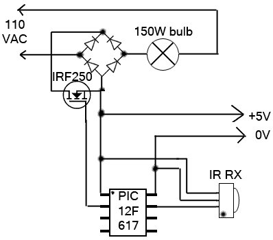
Remote controls transmit data on an modulated infrared beam. An infrared receiver IC separates the modulated beam into a clean stream of 0s and 1s. The data stream is decoded by a microcontroller and sent to a computer over a USB connection. Software processes the codes and triggers actions on the computer.
![How-to USB remote control receiver]() Background
Background
Computer infrared receivers
The oldest PC infrared receiver design uses a receiver IC to toggle a serial port pin, usually DCD. This design probably originated on Usenet, and it’s still the most popular on the web: Engadget, Instructables, etc. These aren’t true serial devices because they don’t send data to the PC. Instead, a computer program times pulses on the serial port and demodulates the signal. This is a super simple design, but it depends on direct interrupt access and timing precision that’s no longer available in Windows. Linux or Mac users can try this receiver, if you still have a serial port. We couldn’t get this type of receiver to work with the serial port on a modern Windows XP PC, and don’t expect the precise timing to transfer through a USB->serial converter.
Some more advanced infrared receivers are true serial port devices that measure or decoding infrared signals before sending data to the computer. The UIR/IRMan and UIR2 incorporate a classic PIC 16F84, but don’t provide firmware and/or source code. These devices should work on a modern computer, through a USB->serial converter if necessary. The USBTINY and USBIRBOY are native USB devices, but lack wide support.
Receiver software
Regardless of receiver type, the computer needs a program to listen for incoming remote commands and convert them to actions on the computer. Linux and Mac users have LIRC, which supports a bunch of different receiver types. Windows users are a bit less fortunate. WinLIRC is an abandoned Windows port of LIRC for simple interrupt-based serial port receivers; WinLIRC was last developed in 2003. Girder was originally a freeware PC automation utility, but has become expensive bloatware with a 30 day trial. Fortunately, the last freeware version of Girder (3.2.9b) is still available for download.
Working with IR remote protocols
Decoding IR signals
Remote controls encode commands in the spacing or timing of a 38KHz carrier pulse, [San Bergmans] has an explanation of the principals involved. An infrared receiver IC separates the data stream from the carrier. Our job is to decode the data stream with a microcontroller. There are dozens of remote control protocols, but Phillips’ RC5 is widespread and commonly used by hobbyists.
RC5 is stream of 14 equal length bits of exactly 1.778ms per bit time. A pulse during the first half of the bit time represents 0, a pulse in the second half represents 1. This scheme is called Manchester coding.
We used a logic analyzer to examine the output of a Happauge WinTV remote control, a known RC5 remote. The diagram shows two presses of the 1 button, and two presses of the 2 button; note that the output is inversed and the Manchester coding is backwards from the above description.
The first two bit times are start bits, followed by a toggle bit. The toggle bit inverses each time a button is pressed so the receiver can tell the difference between a hold and a repeated press. The next 5 bits are the address (0b11110=0x1E), followed by the command (0b000001=0x01, 0b000010=0x02). A backwards compatible extension to RC5 uses the second start bit as command bit 7.
Representing remote codes to the computer
Looking at previous designs, we saw three general methods of communicating remote commands to a computer:
- Protocol specific receivers decode one protocol, and send actual decoded commands to the PC
- A more general type of receiver measures the timing and spacing of each pulse and sends the full waveform to the PC for analysis.
- Some receivers create a unique hash for a signal, but don’t actually include enough data to fully recreate the waveform.
While our preference is towards the general hash method, our only remote uses RC5 and it was more interesting to build an RC5 specific decoder. We describe modifications for a more general version in the firmware section.
Computer interface protocol
We didn’t want to write our own receiver software or driver, so we looked for an existing, well established communication protocol to imitate. The UIR/IRMAN/IRA/CTInfra/Hollywood+ type receiver is supported by Girder and LIRC, and uses a simple serial protocol with handshake:
- The device is initialized by the DTS and DTR pins of the serial port. We don’t have these and don’t care.
- The computer sends “IR”, with an optional delay. The device replies “OK”. We’ll just send “OK” on every “R”
- Remote control codes are sent as a unique six byte hash. We’ll decode an RC5 signal and send the actual values, but a generic hash could be used instead.
This protocol is for a serial port device, but our USB receiver will appear as a virtual serial port and the program won’t know the difference.
Hardware
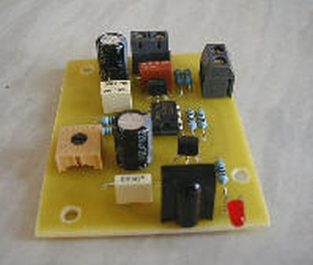
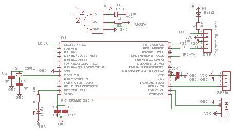
Click here for a full size schematic (png). Our receiver is based on a USB enabled PIC 18F2455 microcontroller, the smaller, cheaper version of the 18F2550. The 18F family is programmable with the hobbyist favorite JDM-style programmers if a diode is used to drop VPP to a safe level. The PIC gets one decoupling capacitor (C1), and a diode (D1) and resistor(R1) on the ICSP programming header. We exposed the serial port on a pin header for debugging or a mixed USB/serial port version using a MAX RS232 transceiver IC.
The USB peripheral requires a 20MHz external clock (Q1, C5,6), and a .220uF capacitor. We faked the capacitor using 2 x .1uF decoupling capacitors (C2,3). A 3mm LED (LED1) and a 330ohm current limiting resistor (R2) show USB connection status.
We used a TSOP-1738 infrared receiver IC which calls for a 4.7uF decoupling capacitor (C4). If you can’t find this particular IC, any receiver listed here should work. The TSOP-1738 output is the inverse of the received signal, it pulls to ground when a pulse is detected, so a pull-up resistor (R3) holds the pin high when no signal is present. Check if you use a different receiver, you may need to use a pull-down resistor and reverse the Manchester decoding routine in the firmware.
![How-to USB remote control receiver]()
|
Part
|
Description
|
|
IC1
|
|
|
–
|
|
|
C1,2,3
|
|
|
C4
|
|
|
C5,6
|
|
|
D1
|
|
|
Q1
|
|
|
R1,3
|
|
|
R2
|
|
|
TSOP
|
|
|
USB
|
|
|
SER
|
|
|
ICSP
|
|
Firmware
The firmware is written in C using Microchip’s free demonstration C18 compiler. Firmware and source are included in the project archive (zip).
We used version 2.3 of Microchip’s USB stack to create a USB serial port using the default drivers already available on most systems. The USB stack has simple functions to enumerate the USB device and transfer data between device and host. It only took a few pin changes to get the CDC demonstration working on our custom hardware.
Our implementation of the UIR/IRMAN/IRA/CTInfra/Hollywood+ protocol simply responds to the letter ‘R’ with ‘OK’. This should satisfy the handshake requirements of any implementation of this protocol.
We chose to specifically decode RC5 (and RC5x) because it’s a widely used protocol, and the only type of remote we have to work with. Most of the decoding is done in the interrupt handler:
For more detail: How-to USB remote control receiver
Current Project / Post can also be found using:
- usb pic remote control circuit
The post How-to: USB remote control receiver using pic microcontoller appeared first on PIC Microcontroller.